Dashboard
The machine as it is now, built from widgets you place yourself. The heading names the configuration that is loaded — its title, its short name, and a MODIFIED badge when the live machine has drifted from what was saved.
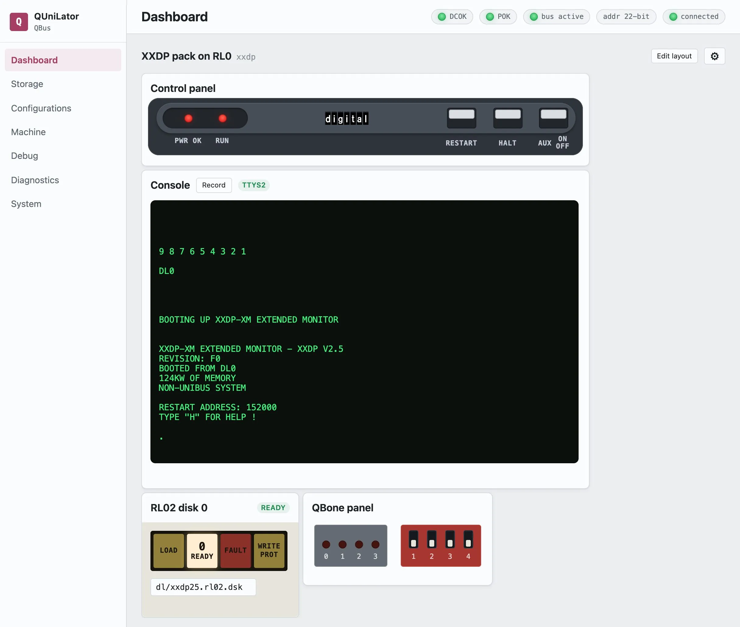
Control panel
Section titled “Control panel”The lamps and switches of a PDP-11/03 bezel, and the only place the machine is started and stopped.
| PWR OK | the logical power flag. Lit means the machine is switched on. |
| RUN | the CPU is executing — powered, with HALT released. |
| RESTART | momentary. Runs the processor again from its power-up vector. |
| HALT | two-position, like the front-panel toggle. Down stops the CPU; up releases it. |
| AUX ON/OFF | two-position. This is the power switch — it drives the logical DC power flag, and it is what brings up a machine that came up dark. |
Front panel
Section titled “Front panel”The four activity LEDs and four DIP switches on the card itself.
The switches are read once, when the service starts, to choose which configuration to load — so changing them here shows you their position but does not reselect a machine. That takes a restart of the service. See Power-on DIP.
Console
Section titled “Console”The machine’s serial console as a terminal in the page. The badge says which line it is showing — TTYS2 for the real console of a CPU that has its own serial line, or the emulated DL11 channel otherwise.
Record captures the session to a file on the board: what the machine printed and what was typed at it, whoever typed it. The recordings are listed on System.
Device widgets
Section titled “Device widgets”One widget per device, each carrying the controls the real unit had. A device gets the widget its model calls for, and otherwise the one its class shares:
| RL01/RL02 | the drive’s own panel — LOAD, READY, FAULT, WRITE PROT, and the unit number |
| RA81 and other MSCP volumes | RUN/STOP, FAULT, READY, WRITE PROT, and the A/B port buttons |
| RX01/RX02 | floppy drives |
| Tapes | load, unload and the write ring |
| Memory | the range claimed, out of the board’s own DDR |
| MRV11-D | the bootstrap ROM and which image it carries |
| DZV11, DHV11 | the serial mux lines, and where each is reachable |
| DELQA, DEUNA | LINK and ACT lamps, the host interface and the station address |
| VCB01 | the graphics framebuffer |
| Processors | an emulated CPU’s own state |
The field under a drive is the image it holds — swapping a pack is editing that field.
Laying it out
Section titled “Laying it out”Edit layout moves and resizes the widgets, with Save layout and Revert. The arrangement is stored with the configuration, so each machine remembers how you like to look at it, and an exported configuration carries its layout to whoever you send it to.
The cog beside it opens the configuration this dashboard is showing.